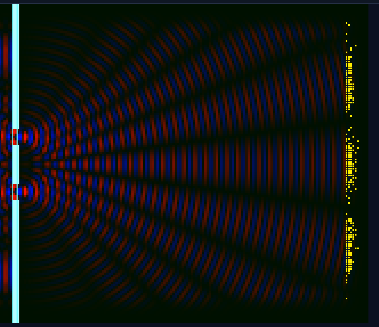
Maxwell (TEz Yee) Double‑Slit in CBF
A 2‑D TEz FDTD solver drives a plane wave into a bright metal wall with two slits. The right side shows interference and a commit detector. Everything is phrased in CBF terms: translation flux Π is T, stored field energy density u is M, loss σ drains M, and the detector commits events with weights proportional to Π⋅n (or selectable alternatives).
How this maps to CBF
Π (Poynting) is the per‑cell translation budget T. The field energy density u is the maintenance budget M. The absorber implements M drain via σE². The NodeGraph on the right approximates the Event Ledger, selecting commits along the screen with probability ∝ weight (default Π⋅n). Slit edges act as geometry that diversifies directions, enabling phase alignment on the detector, where commit frequency appears as bright rows.
CBF ↔ Maxwell Mapping
T(translation) = Poynting fluxΠ = E×H→ arraysPix,PiyM(maintenance) = energy densityu = ½(εE² + μH²)→ arrayuArrMdrain =σE²(absorber)- Ledger commits = stochastic hits ∝ chosen weight (default
|Π⋅n|)
60‑Second Tour
- Left of slits: plane source + reflection → standing pattern (budget parked in M).
- At slits: edges diversify directions, enabling phase match downstream.
- Right of slits: interference fans; commits cluster where phases align (bright yellow rows).
- Brightness = visual gain only.
- Switch commit weight:
Π⋅n≈screen flux,|Π|≈total flow,u≈stored energy.
What to expect
- Before the slits: cavity interference from the plane source reflecting on the wall, a budget build‑up zone (more M).
- After the slits: two secondary lobes that interfere; detector commits cluster where phases beat‑match.
- Brightness slider: multiplies post‑normalization amplitude so high‑frequency runs stay visible without clipping low‑freq runs.
Settings
| Parameter | Default | Notes |
|---|---|---|
| Frequency | 30 | Wavelength ≈ Nx / f. |
| Loss σ | 0.8 | Absorbing boundary strength (M drain). |
| Commit probability | 0.5 | Throttle for NodeGraph commits. |
| Commit weight | |Π⋅n| | Detector weighting mode (u, |Π|, |Π⋅n|, |Ez|²). |
| Brightness | 1.5 | Gain after auto‑scaling, keeps high‑f runs visible. |
| Slits | On | Bright, thick wall with two clear openings by default. |
Key Code
Standard TEz Yee with PEC mask for the bright wall and slits.
Π emerges from fields as translation, u as maintenance. The PEC mask is a hard constraint that redirects T, creating the direction diversification needed for interference.
Wall width increased, cyan guides added, and a post‑normalize brightness control keeps high‑frequency runs visible.
The wall is a geometric constraint, not a source. The gain knob is purely visual, it does not change Π or u, only how we render accepted information.
Π is translation, u is maintenance. The detector picks commits stochastically with weight ∝ selected metric.
The residual tracks local conservation between T outflow, M change, and σ drain. Commits are outcomes, not field accumulation.
Quiet the pre‑slit cavity by adding a thin σ strip behind the source line.